

 NinjaCalc
MIPI CSI Communication Protocol

The CSI communication protocol defines a physical, electrical and logical interface between a camera and host processor. The protocol spans everything from the physical layer up to the application layer. The CSI communication protocol is commonly used between cameras in smartphones and the main processor, in VR headsets, drones, and non-camera related sensing applications (such as mmWave sensors).
The specification documents of the MIPI communication protocol are only available to paying members of the MIPI Alliance.1 The official MIPI site is at https://www.mipi.org/.
MIPI also defines the MIPI DSI (Display Serial Interface) protocol, which is similar but different in that it is used to connect processors to displays instead of cameras.2
Versions
MIPI CSI-1
The MIPI CSI-1 specification was released in 2004. It is the camera serial interface — a camera parallel interface was released at the same time. It used differential signalling and supported transfer rates up to 1 Gbps.3
It was quickly superseded by the MIPI CSI-2 specification which was released in 2005.
MIPI CSI-2
The MIPI CSI-2 v1.0 specification was released in 2005.4 It is still being updated, with the v4.2 release in Dec 2025. It uses either D-PHY or C-PHY for the physical layer (see Physical Layers below).
Below is a table summarizing the major versions of the MIPI CSI-2 specification:
| Version | Release Date | Comments |
|---|---|---|
| v1.0 | 2005 | Initial release. |
| v2.0 | Apr 2017 | Added support for RAW-16 and RAW-20 colour depth. Increased the number of virtual channels from 4 to 32. Introduced latency reduction and transport efficiency (LRTE). Added differential pulse-code modulation (DPCM) compression. Added scrambling to lower power spectral density.2 |
| v3.0 | Sep 2019 | Added Unified Serial Link (USL), Smart Region of Interest (SROI), End-of-Transmission Short Packet (EoTp) and RAW-24 colour depth. |
| v4.2 | Dec 2025 | Latest version as of mid-2026.5 |
MIPI CSI-3
MIPI CSI-3 has never been widely adopted, and CSI-2 still remains the most common MIPI camera interface.
A basic CSI-3 v1.1 link configuration using four forward lanes and one reverse lane (10 total wires) can support up to 14.88 Gbps (usable bit rate, including 8B10B and UniPro overhead) in the forward direction and typically supports 1 Mbps or more in the reverse direction.1
| Version | Release Date | Comments |
|---|---|---|
| v1.1 | Mar 2014 |
Physical Layers
The MIPI CSI-2 protocol can use either D-PHY or C-PHY as the physical layer. D-PHY was the only option up until CSI-2 v1.3 (2014), which added the ability to use the (then new) C-PHY.6 Both D-PHY and C-PHY are separate specifications set by the MIPI Alliance, and they are not exclusive to CSI. The same PHYs are shared by several MIPI protocols:
| PHY | Used By | Notes |
|---|---|---|
| D-PHY | CSI-2 (cameras), DSI-2 (displays)7 | The same differential lanes + clock lane design drives both. A phone SoC typically has D-PHY blocks on both the camera input and the display output. Supports interconnect lengths up to 4 m.7 |
| C-PHY | CSI-2, DSI-28 | Same trio concept for both cameras and displays. |
| M-PHY | CSI-31, UniPro, UFS storage9, DigRF | M-PHY outlived CSI-3’s failure because JEDEC’s UFS (the flash storage in most modern phones) runs on UniPro over M-PHY.9 |
| A-PHY | CSI-2 and DSI-2 (tunnelled via protocol adaptation layers, PALs)10 | Long-reach (up to 15 m) asymmetric link for automotive (ADAS, autonomous driving, infotainment).10 Carries cameras/displays over a single cable, competing with GMSL and FPD-Link. |
D-PHY
D-PHY uses differential signalling and is the most common PHY.
- Lane structure: One dedicated clock lane plus 1-4 data lanes. Each lane has two wires (differential pair). Data lanes are unidirectional in high-speed mode.
- Clocking: The clock is sent on a dedicated clock lane. The data lanes are sampled relative to the clock lane (on both edges, i.e. DDR). At high speed the skew between the clock and data lanes becomes a limiting factor. D-PHY v3.5 added an optional embedded clock mode which frees up the clock lane to carry data instead.7
- Signalling: Interestingly, there are two different signalling modes used on the same wires:
- HS (high-speed) mode: The data is sent as a ±200 mV signal riding on a 200 mV common mode voltage. High-speed mode is used for bursts of pixel data.
- LP (low-power) mode: The data is sent as a single-ended signal (0 V or 1.2 V). This is used between high-speed bursts to send control information.
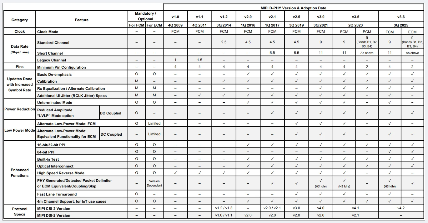
- Speed: The speed depends greatly on the D-PHY version. v2.0 (Q1 2016) supports 4.5 Gbps per lane, while the newer v3.0 (released in 2021) supports 11 Gbps per lane in a “Short channel” (9 Gbps in standard).11
The below table shows the history of the D-PHY specification versions and when specific features were added (as of June 2026)7:
C-PHY
C-PHY is a more exotic encoding than D-PHY that uses a special 3-wire “trio” encoding scheme. I can only presume it’s less common than D-PHY because D-PHY came first, is simpler and works well enough for most applications. But C-PHY could be useful for really high-bandwidth cameras and/or to reduce the total pin count when connecting a processor to many cameras (e.g. drones, autonomous vehicles).
C-PHY has the following characteristics:
- Lane structure: 3 wires per lane (a lane is called a trio).
- Clocking: There are no dedicated clock wires, the clock is embedded in the data.
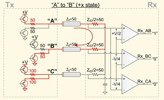
- Signalling: C-PHY uses 3-phase encoding. Each of the 3 wires can be at one of three voltage levels (low, mid, or high). Only the states where all three wires are not at the same level are valid, giving 6 valid states. Data is sent in the transitions between the valid states. At every unit interval (UI, which corresponds to the rate symbols are sent), the 3 wires must change state. From any original state there are 5 possible new states, so each transition carries a maximum of bits of information. The official spec maps 16 bits onto 7 symbol transitions, giving bits per symbol.12 In practice, this means the encoder takes in 16-bit words, and outputs 7 symbols (each symbol would be internally represented by 3 bits before reaching the analogue driver circuitry) which are then sent on the 3 wires.
The schematic below shows a MIPI C-PHY transmitter and receiver. You can see that the receiver uses three differential receivers, one connected across each pair of wires in the trio (A-B, B-C and C-A).12
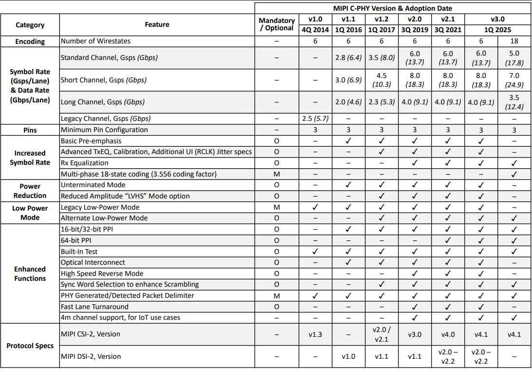
The C-PHY specification supports symbol rates of up to 6 Gsps (gigasymbols per second) per trio. Each symbol encodes ≈2.28 bits, giving an effective bit rate of ≈13.7 Gbps (gigabits per second) per trio. With up to three trios, the total bandwidth is ≈41 Gbps.8,13 Newer versions of the spec also define an 18-wirestate mode encoding 3.556 bits per symbol at symbol rates of up to 5 Gsps, raising the three-trio total to ≈53 Gbps.8
The different versions and what was supported in each is summarized in the table below (as of June 2026).8
MIPI A-PHY
The MIPI A-PHY is a long-reach (up to 15 metres) physical layer designed for automotive applications such as ADAS and ADS. It supports both point-to-point and daisy chain topologies.10 Prior to A-PHY, proprietary bridges were used to extend the reach of MIPI CSI-2 and DSI-2 using the D-PHY or C-PHY. One goal of A-PHY is to replace these proprietary bridges with a standardised solution.
A-PHY was adopted as IEEE standard 2977-2021 in June 2021.10
v1.0 and v1.1 allow for 5 downlink speed gears of 2, 4, 8, 12 and 16 Gbps, and 2 uplink speed gears of 100 and 200 Mbps. v2.0 added 24 and 32 Gbps downlink speed gears and a 1.6 Gbps uplink speed gear.10
Footnotes
-
MIPI Alliance (2021, Jan 21 snapshot). MIPI Camera Serial Interface 3 (MIPI CSI-3) [specification page]. Retrieved 2026-07-21, from https://web.archive.org/web/20210121205209/https://www.mipi.org/specifications/csi-3. Archived copy; the original page at mipi.org has since been removed. ↩ ↩2 ↩3
-
Spinel Electronics. MIPI CSI vs MIPI DSI: Key Differences and Choosing the Right Interface for Your Camera. Retrieved 2026-07-21, from https://www.spinelelectronics.com/mipi-csi-vs-mipi-dsi/. ↩ ↩2
-
Sinoseen (2024, May 29). Understanding MIPI Interface, Protocol, and Standards: A Comprehensive Guide. Retrieved 2026-07-22, from https://www.sinoseen.com/what-is-mipi-protocol-and-standards. ↩
-
Wikipedia (2026, Feb 23). Camera Serial Interface [wiki]. Retrieved 2026-07-21, from https://en.wikipedia.org/wiki/Camera_Serial_Interface. ↩
-
MIPI Alliance. Current Specifications [website]. Retrieved 2026-07-21, from https://www.mipi.org/current-specifications. ↩
-
MIPI Alliance (2015, Feb 18). MIPI Alliance Updates its Widely Adopted CSI Specification to Bring High-Resolution Imaging, Richer Color and Video to Mobile and Mobile-Influenced Applications [press release]. Design & Reuse (mirror). Retrieved 2026-07-22, from https://www.design-reuse.com/news/985-mipi-alliance-updates-its-widely-adopted-csi-specification-to-bring-high-resolution-imaging-richer-color-and-video-to-mobile-and-mobile-influenced-applications/. ↩
-
MIPI Alliance. MIPI D-PHY [specification page]. Retrieved 2026-07-22, from https://www.mipi.org/specifications/d-phy. ↩ ↩2 ↩3 ↩4 ↩5
-
MIPI Alliance. MIPI C-PHY [specification page]. Retrieved 2026-07-22, from https://www.mipi.org/specifications/c-phy. ↩ ↩2 ↩3 ↩4 ↩5
-
MIPI Alliance. MIPI M-PHY [specification page]. Retrieved 2026-07-22, from https://www.mipi.org/specifications/m-phy. ↩ ↩2
-
MIPI Alliance. MIPI A-PHY [specification page]. Retrieved 2026-07-22, from https://www.mipi.org/specifications/a-phy. ↩ ↩2 ↩3 ↩4 ↩5
-
MIPI Alliance (2021, Sep 2). MIPI D-PHY v3.0 Doubles Data Rate of Physical Layer Interface While Extending Power Efficiency [press release]. Retrieved 2026-07-22, from https://www.mipi.org/press-releases/mipi-d-phy-v3.0-doubles-data-rate-of-physical-layer-interface-while-extending-power-efficiency. ↩
-
George Wiley, Qualcomm Technologies (2016). Implementing MIPI C-PHY - Unique properties of the MIPI C-PHY physical layer and system-level benefits and values for Camera and Display interfaces [conference presentation]. MIPI DevCon 2016. Retrieved 2026-07-22, from https://mipi.org/sites/default/files/MIPI-DevCon-2016-Implementing-MIPI-C-PHY.pdf. ↩ ↩2 ↩3
-
Arasan Chip Systems. MIPI C-PHY v2.0 + D-PHY v2.5 Combo IP Core [product page]. Retrieved 2026-07-21, from https://www.arasan.com/product/mipi-c-phy/. ↩