

 NinjaCalc
LED Matrix Displays

LED matrix displays (also called LED dot matrix displays) are displays made from a 2D grid of LEDs, with each LED acting as one pixel. Because the resolution is usually low (common sizes are 8x8, 16x16 and 32x32), they are used to show text, symbols, simple animations and low-resolution “pixel art” rather than detailed images.
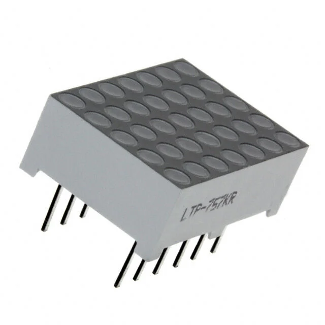
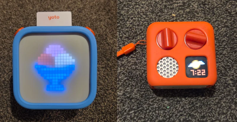
Unlike LCDs and electrophoretic displays, every pixel is self-emissive, which gives them high brightness, wide viewing angles and good visibility in the dark. They are found in scrolling message signs, clocks, audio spectrum displays, bus/train destination boards and consumer products such as the Yoto kids audio player (which uses a 16x16 RGB LED matrix to show pixel-art icons).2
How They Work
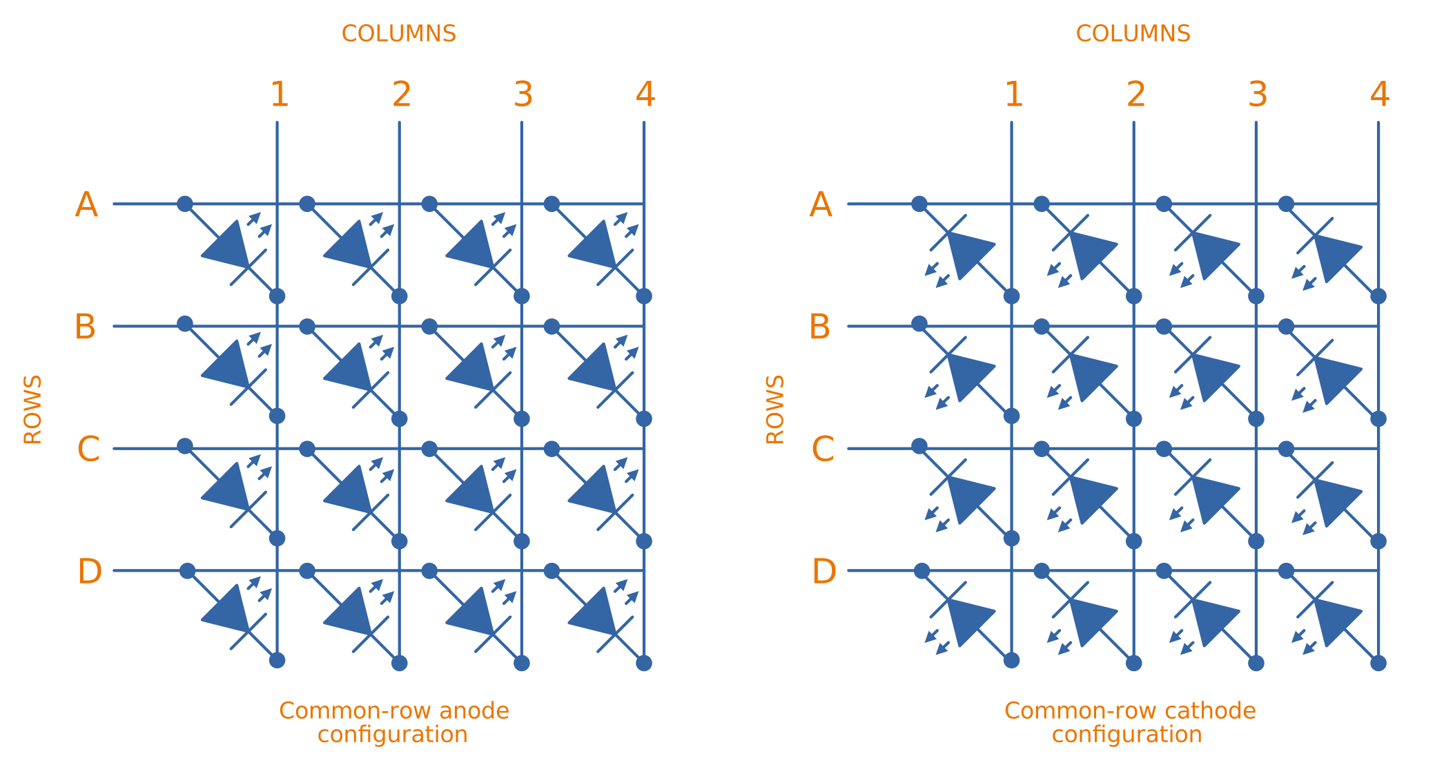
The simplest way to drive a grid of LEDs would be to wire each one to its own microcontroller pin, but this doesn’t scale — an 8x8 matrix would need 64 pins. Instead, the LEDs in a matrix are wired in rows and columns. In a row-cathode arrangement, all of the anodes in a column are connected together and all of the cathodes in a row are connected together (or vice versa for row-anode). An matrix then only needs connections, e.g. 16 pins for an 8x8 matrix instead of 64.
The trade-off is that you can no longer turn on an arbitrary pattern of LEDs all at once, since the LEDs share row and column lines. The solution is multiplexed scanning: the driver turns on one row at a time, sets the column lines to the pattern for that row, then moves on to the next row. This is illustrated in the diagram below. If this scan is repeated fast enough (a full-frame refresh rate of is a good starting point), persistence of vision makes the image appear steady to the human eye. Slower refresh rates can produce visible flicker, especially in peripheral vision, and any refresh rate can show up as banding or strobing when the display is filmed with a camera.
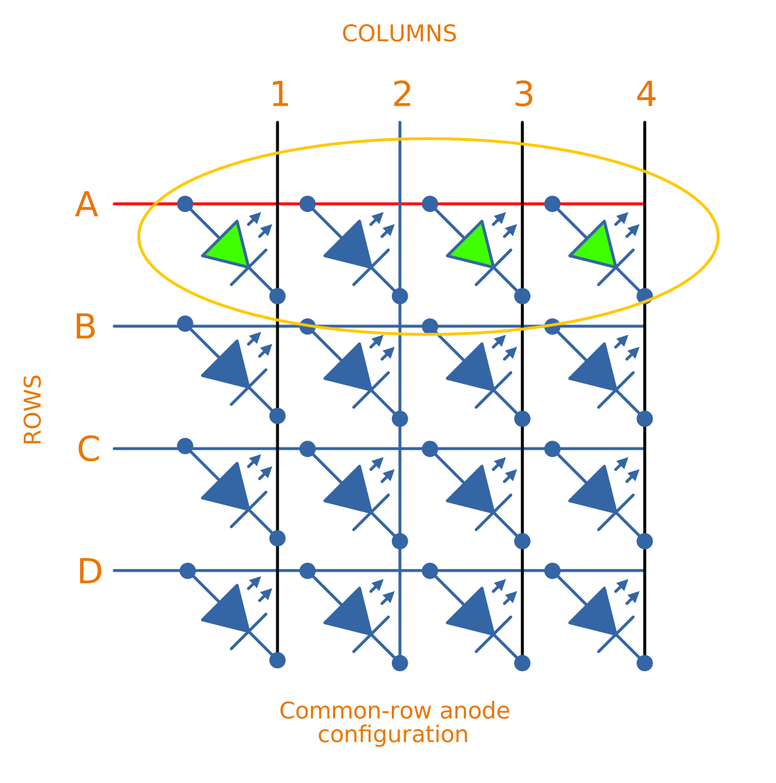
Because each row is only on for of the time (its duty cycle), the peak current through each LED must be roughly times higher than the desired average current to achieve the same apparent brightness. LEDs are usually rated for much higher peak pulse currents than continuous currents, so this works, but it is why dedicated matrix driver ICs with constant-current outputs are preferred over bare microcontroller pins for anything beyond a small hobby matrix.
Charlieplexing is a related technique that exploits the tri-state capability of microcontroller pins to drive LEDs from only pins. It reduces pin count even further, but the duty cycle per LED is worse and the wiring is harder to reason about, so it tends to be used for small indicator arrays rather than full displays.
Driver ICs
Dedicated driver ICs handle the scanning, constant-current drive and brightness control, and present a simple serial interface (SPI or I2C) to the host microcontroller.
Popular examples include:
- MAX7219/MAX7221 (Analog Devices, previously Maxim): Probably the most well-known hobbyist LED matrix driver. It drives an 8x8 monochrome matrix (or 8 seven-segment digits) with a SPI-compatible serial interface, contains an 8x8 static RAM to hold the display data, and sets the segment current with a single external resistor. Devices can be daisy-chained to build longer displays, which is why chains of 8x8 MAX7219 modules are a common way to build scrolling text signs.3
- HT16K33 (Holtek): An I2C driver that can scan up to a 16x8 matrix, with built-in RAM and a key-scan function. It is used on many small “backpack” matrix boards such as Adafruit’s 8x8 matrix backpacks.4
- IS31FL37xx family (Lumissil, previously ISSI): I2C matrix drivers with per-LED PWM brightness control (e.g. the IS31FL3731 drives 144 LEDs with 8-bit PWM each), enabling smooth fades and greyscale effects rather than simple on/off pixels.5
Addressable RGB Matrices
Many modern LED matrix displays, particularly RGB ones, do away with the row/column scanning approach entirely and instead use addressable LEDs such as the WS2812B (commonly known by Adafruit’s brand name NeoPixel) or the SK6812. Each LED package contains its own driver IC and is connected in a single long daisy-chain — the matrix is electrically just a strip of addressable LEDs zig-zagged into a grid. Each pixel holds its own 24-bit colour value, so no scanning is needed and there is no flicker.6
The main design considerations with addressable matrices are:
- Power: each WS2812B can draw up to about at full white, so a 16x16 matrix can theoretically draw over . In practice firmware limits the overall brightness, but the power supply and PCB traces/wiring must be sized carefully.
- Data timing: the single-wire protocol has strict timing requirements (an bit stream), which is usually met with hardware peripherals (SPI, PIO, RMT etc.) rather than bit-banging.
- Mapping: because the chain is usually laid out in a serpentine (zig-zag) pattern, the firmware must map pixel coordinates to the correct index in the chain.
HUB75 Panels
Larger RGB panels (32x32, 64x32, 64x64 and up) used for video walls and signage typically use the HUB75 interface. These panels are scanned matrices: they contain shift-register/latch driver ICs on the back, and the host must continuously clock in row data and step through the row-address lines (labelled A, B, C and up to E, depending on the panel’s scan rate) to refresh the display. Colour depth is achieved by repeatedly re-scanning the panel with binary-coded modulation, so the host needs to sustain a high pixel clock — this is commonly done with an FPGA, or a microcontroller with DMA and plenty of spare CPU time (dedicated driver boards exist for the Raspberry Pi and ESP32).7 The reward is that HUB75 panels are much cheaper per pixel than addressable-LED matrices and can be tiled edge-to-edge into large video displays.
The below image shows the pinout of the standardized HUB75 connector. This is the male 2x8 IDC header.
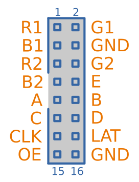
Below is a table describing the pin numbers, signal names and descriptions on the HUB75 connector.
| Pin | Signal | Description |
|---|---|---|
| 1 | R1 | Red data for the top half of the panel |
| 2 | G1 | Green data for the top half of the panel |
| 3 | B1 | Blue data for the top half of the panel |
| 4 | GND | Ground |
| 5 | R2 | Red data for the bottom half of the panel |
| 6 | G2 | Green data for the bottom half of the panel |
| 7 | B2 | Blue data for the bottom half of the panel |
| 8 | E | Row address bit 4. Only used on 1/32-scan panels (e.g. 64x64) — on lower scan-rate panels this pin is ground |
| 9 | A | Row address bit 0 |
| 10 | B | Row address bit 1 |
| 11 | C | Row address bit 2 |
| 12 | D | Row address bit 3. Not used on 1/8-scan panels (e.g. 32x16) |
| 13 | CLK | Clock. Pixel data on R1/G1/B1/R2/G2/B2 is shifted into the panel’s shift registers on each clock edge |
| 14 | LAT | Latch (a.k.a. strobe, STB). Transfers the shifted-in row data to the output drivers |
| 15 | OE | Output enable (active low). Blanks the display, e.g. whilst switching row addresses |
| 16 | GND | Ground |
Note that the connector carries no power. HUB75 panels have a separate high-current 5V power connector, as the logic connector could not handle the many amps a large panel can draw.
Footnotes
-
DigiKey. LTP-757KR Lite-On Inc. | LED Dot Matrix and Cluster [product page]. Retrieved 2026-07-03, from https://www.digikey.co.nz/en/products/detail/liteon/LTP-757KR/408228. ↩
-
Yoto. Yoto Player [product page]. Retrieved 2026-07-02, from https://us.yotoplay.com/products/yoto-player. ↩
-
Analog Devices. MAX7219/MAX7221 Serially Interfaced, 8-Digit LED Display Drivers [datasheet]. Retrieved 2026-07-02, from https://www.analog.com/media/en/technical-documentation/data-sheets/MAX7219-MAX7221.pdf. ↩
-
Holtek. HT16K33 RAM Mapping 16x8 LED Controller Driver with keyscan [datasheet]. Retrieved 2026-07-02, from https://www.holtek.com/webapi/116711/HT16K33Av102.pdf. ↩
-
Integrated Silicon Solution, Inc. (2013, Apr 22). IS31FL3731 Audio Modulated Matrix LED Driver [datasheet]. Retrieved 2026-07-06, from https://www.mouser.com/pdfDocs/31FL3731-258525.pdf. ↩
-
Worldsemi. WS2812B Intelligent control LED integrated light source [datasheet]. Retrieved 2026-07-02, from https://cdn-shop.adafruit.com/datasheets/WS2812B.pdf. ↩
-
Phillip Burgess. 32x16 and 32x32 RGB LED Matrix [guide]. Adafruit. Retrieved 2026-07-02, from https://learn.adafruit.com/32x16-32x32-rgb-led-matrix. ↩