Fuel Gauge ICs

Fuel gauge ICs (also called gas gauges, coulomb counters or battery state-of-charge ICs) are integrated circuits that estimate how much usable charge is left in a battery and report it to a microcontroller (usually over I2C, SMBus or 1-Wire). They are the “fuel gauge” for a battery-powered product — turning the messy, non-linear, temperature- and age-dependent behaviour of a cell into a simple state-of-charge (SoC) percentage and a remaining-capacity estimate in mAh.
It is worth being clear about what a fuel gauge IC is not:
- It is not a charger. Charging (and regulation) is the job of a power management IC (PMIC).
- It is not a protection device. Over-charge, over-discharge and over-current protection is the job of a protection circuit module (PCM).
- It is not a mains power meter. Isolated measurement of AC mains power is the job of a power monitor IC.
A fuel gauge just measures the battery and reports its state. In a complete battery management system (BMS) it sits alongside the charger and protection circuitry.
Why Fuel Gauging Is Hard
You might think you can read a battery’s state-of-charge straight from its terminal voltage. For some chemistries (e.g. lithium-ion) the discharge curve is deliberately flat over most of the usable range, so a small voltage error maps to a large SoC error. On top of that, the terminal voltage:
- Sags under load because of the cell’s internal resistance ().
- Rises when charging, again due to the internal resistance.
- Shifts with temperature.
- Drifts as the cell ages and its full-charge capacity fades.
Gauging Methods
Voltage-Based (OCV Lookup)
The simplest method is to just measure the battery’s voltage, then convert this into an approximate SoC using a lookup table or curve. It needs no external sense resistor and draws very little current, but is rather inaccurate due to:
- The mapping from voltage to SoC becomes very imprecise for chemistries with flat discharge curves (during the middle part of the discharge cycle, the voltage changes very little as the battery discharges).
- The terminal voltage is affected by load (internal resistance effects), temperature and age, so the same voltage can correspond to very different SoC values in different conditions.
The good news is that this method normally does not require a dedicated fuel gauge IC — you can just measure the voltage with an ADC you already have in your microcontroller.
A resistor divider is normally needed to step down the battery voltage to the ADC’s input range. For power constrained designs the resistor divider resistances should be as high as possible (e.g. MΩ range) to minimise the current drawn from the battery, but this makes the measurement more susceptible to noise (and takes longer to charge up the ADC’s internal capacitance).
Sometimes a N-channel MOSFET is used to disconnect the resistor divider when not measuring, to eliminate this current draw. This is shown in the schematic below. The gate of the MOSFET is driven by a GPIO pin on the microcontroller, which is driven high when a measurement is needed and low otherwise. is a pull-down resistor to ensure the MOSFET is off when the GPIO is tri-stated (e.g. during MCU reset).

You will normally need to add a small delay in firmware between enabling the MOSFET and taking the ADC measurement, to allow the ADC’s internal sample-and-hold capacitor to charge up through the high-value resistor divider. The required delay depends on the ADC’s input impedance and the values of and , and is typically up to a few milliseconds.
Voltage-Based With Cell Modelling
An improvement on basic voltage-based estimation is to also model the cell dynamics. Modern voltage-based gauge ICs (e.g. Analog Devices’ ModelGauge) improve on naive OCV lookup by modelling the cell’s dynamics to correct for load and relaxation. An example of how one of these ICs would be used is shown in the below schematic. These are more accurate than simple OCV lookup, but not as accurate as those which use a current-sense resistor and perform coulomb counting.

Coulomb Counting
A coulomb counter integrates the current flowing in and out of the battery (measured across a low-value external sense resistor, typically 5–20 mΩ) to track the net charge transferred:
This is very accurate over the short term, but it has two weaknesses: it accumulates error over time (offset error in the current measurement integrates into ever-growing drift), and it only measures changes in charge — it has no absolute reference. It therefore needs periodic recalibration against known reference points, usually a full charge or a full discharge.
Impedance Tracking / Hybrid Models
The most accurate ICs combine OCV lookup, coulomb counting and a model of the cell’s internal impedance, and they continuously learn the cell’s full-charge capacity as it ages. TI’s Impedance Track™ and Analog Devices/Maxim’s ModelGauge m5 are examples. These typically require a learning/optimisation cycle and a configuration profile matched to the specific cell, but they track SoC accurately across load, temperature and the life of the battery.
Examples
TI BQ27441-G1
The TI BQ27441-G1 is a single-cell Li-ion fuel gauge that lives on the system board (rather than inside the battery pack) and uses TI’s patented Impedance Track™ algorithm to report remaining capacity and state-of-charge over I2C.1 It uses a low-value (10 mΩ) external sense resistor for coulomb counting and ships with a configurable battery profile.
Analog Devices MAX17048
The MAX17048 is a low-power single-cell fuel gauge that uses Analog Devices’ (formerly Maxim) voltage-based ModelGauge algorithm. Its key selling point is that it needs no external current-sense resistor — it estimates SoC purely from the cell voltage using its internal model — which saves board area and the power lost in a sense resistor. It draws only a few microamps, making it well suited to low-power designs.2
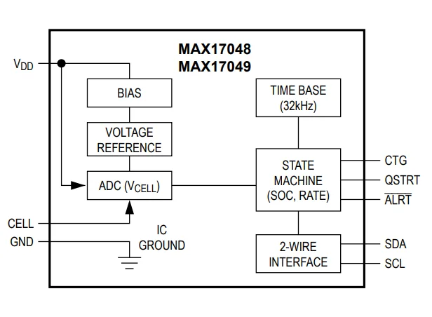
The MAX17049 is the same as the MAX17048 but works with two Lithium cells in series.2
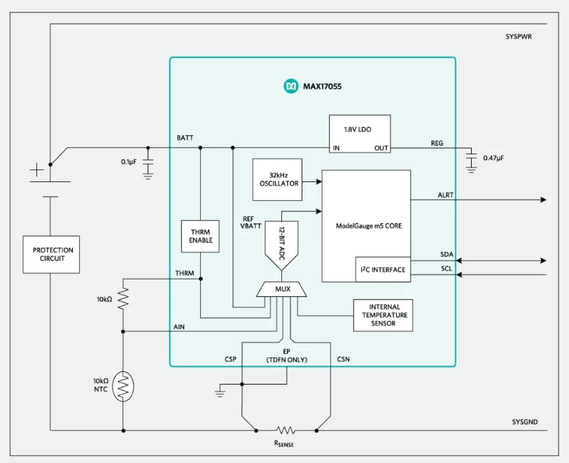
Analog Devices MAX17055
The MAX17055 is an advanced coulomb-counting + modelling fuel gauge IC from Analog Devices. It uses the ModelGauge m5 EZ algorithm, which combines coulomb counting with cell modelling (via a low-value external sense resistor) to get the short-term accuracy of coulomb counting and the long-term robustness of voltage-based modelling. The quoted accuracy from the datasheet is that over 300 different batteries, 97% of the tests had a SoC error of less than 3% after the first cycle.3
It draws 7 uA of operating current and communicates over I2C. It is designed for single-cell Li-ion batteries.3
It supports the following Lithium chemistries:3
- Lithium Cobalt Oxide (LCO):
ModelID = 0. This covers a large majority of consumer Li-ion batteries. - Lithium NCR or NCA cells:
ModelID = 2. - Lithium iron-phosphate:
ModelID = 6. The datasheet claims that LiFePO4 is a challenging chemistry and custom characterisation is recommended.
Footnotes
-
Texas Instruments (2017, Dec). bq27441-G1 System-Side Impedance Track™ Fuel Gauge [datasheet]. Retrieved 2026-06-24, from https://www.ti.com/lit/ds/symlink/bq27441-g1.pdf. ↩
-
Analog Devices. MAX17048/MAX17049 3µA 1-Cell/2-Cell Fuel Gauge with ModelGauge [datasheet]. Retrieved 2026-06-24, from https://www.analog.com/media/en/technical-documentation/data-sheets/MAX17048-MAX17049.pdf. ↩ ↩2 ↩3
-
Analog Devices (2017, Jan). MAX17055 7µA 1-Cell Fuel Gauge with ModelGauge m5 EZ [datasheet]. Retrieved 2026-06-24, from https://www.analog.com/media/en/technical-documentation/data-sheets/MAX17055.pdf. ↩ ↩2 ↩3 ↩4