

 NinjaCalc
Current Sources And Sinks

Current sources and current sinks are electronic circuits which allow a fixed amount of current to flow through it, irrespective of the voltage across it. A current source (or sink) is not a single passive component, but a small circuit usually made from an active element (transistor, op-amp) and a few passives (such as resistors). Current sources/sinks are used as a sub-circuit in many larger circuit designs.
Uses of current sources:
- Driving LEDs (especially high power LEDs).
- Biasing other circuit elements (e.g. providing a stable bias current for a transistor stage).
- Charging capacitors to provide a linear increase in voltage across it (e.g. to make a sawtooth or triangular waveform).
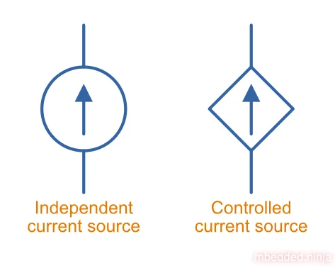
Current sources are very common in circuit design, and as such are usually drawn using schematic symbols as shown below. An independent current source is one which has a predetermined fixed set current. A controlled (or dependent) current source is one which is determined by another measurable value in the circuit, usually a voltage (e.g. ). You may have seen a controlled current source symbol in the small-signal model for a BJT. Many analogue IC functional diagrams will show current sources with these symbols, hiding the discrete components they are made from.
The compliance of a current source is the voltage range that the current source can operate over and function correctly. Outside of this range, either components are damaged (maximum voltage ratings are exceeded) or the current falls out of regulation.
Current sources may either provide power into a circuit (like a power supply), or require external power to operate.
Output Impedance
The quality of a current source is measured by its output impedance . This is how much the output current changes when the voltage across the source changes. It is defined as:
An ideal current source outputs the same current no matter the voltage across it, so and . A real current source has some finite (but hopefully very large) output impedance (the higher the better). For a JFET constant-current diode, for example, the output impedance is the inverse of the output conductance , i.e. .
Measuring Output Impedance (Two-Point DC Method)
Because , you can measure it by deliberately changing the voltage across the source and seeing how much the current moves:
- Connect the source to a load and make sure it is operating within its compliance range.
- Measure the output current at output voltage (e.g. set by a known load resistor).
- Change the load resistor (or supply voltage) so the voltage across the source shifts to , and measure the new current .
- Calculate the output impedance:
For a real source the delivered current always moves opposite to the voltage. You raise the voltage and the current droops, lower it and the current rises. So and always have opposite signs and their ratio comes out negative, whichever point you happen to label 1 or 2. We take the magnitude, since that sign only reflects the direction of the change, not a physically negative impedance.
For a better result, take several points across the compliance range and plot against . The slope of that line is , so a nearly flat line means a high output impedance (a good current source).
A few practical points to watch:
- Stay inside the compliance range. If you push the voltage past the compliance limit, the source falls out of regulation and you end up measuring the load and supply instead — which looks like a deceptively low impedance.
- High-impedance sources need sensitive current measurement. A good source can be many , so the current change for a few volts of is tiny. Use as large a as compliance allows, and a low-noise current measurement (benchtop voltmeters work well here).
- Watch for thermal drift. Slow measurements let self-heating and temperature drift shift the current, masquerading as (or swamping) the true impedance. Take readings reasonably quickly, or let the circuit settle at each point.
Child Pages
Types Of Current Source
Current sources and sinks come in a few distinct families. Broadly, they split into independent sources (a fixed, set-and-forget current) and controlled sources (an output current that tracks an input voltage). Each family is covered in detail on its own page:
| Family | What it is | Examples |
|---|---|---|
| Discrete current sources | Simple, independent constant-current circuits built from a single transistor and a few passives. | Zener diode + BJT source, JFET constant-current diode. |
| Voltage-to-current converters | Controlled (transconductance) sources whose output current is proportional to an input voltage. | Op-amp current sink, Howland current pump, current-loop transmitter ICs. |
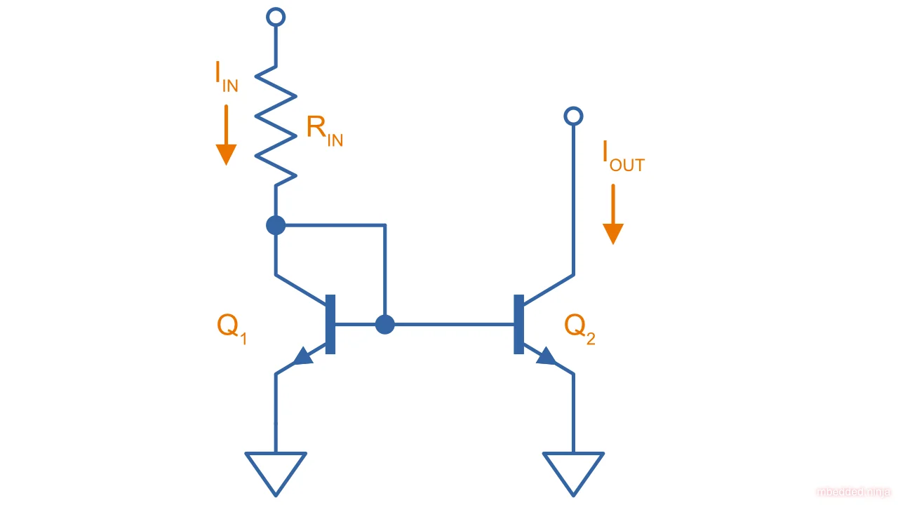
| Current mirrors | Circuits that copy a reference current into one or more output branches. | Basic BJT mirror, buffered feedback mirror; widely used for biasing inside analogue ICs. |